Potter Proof Press Restoration Project
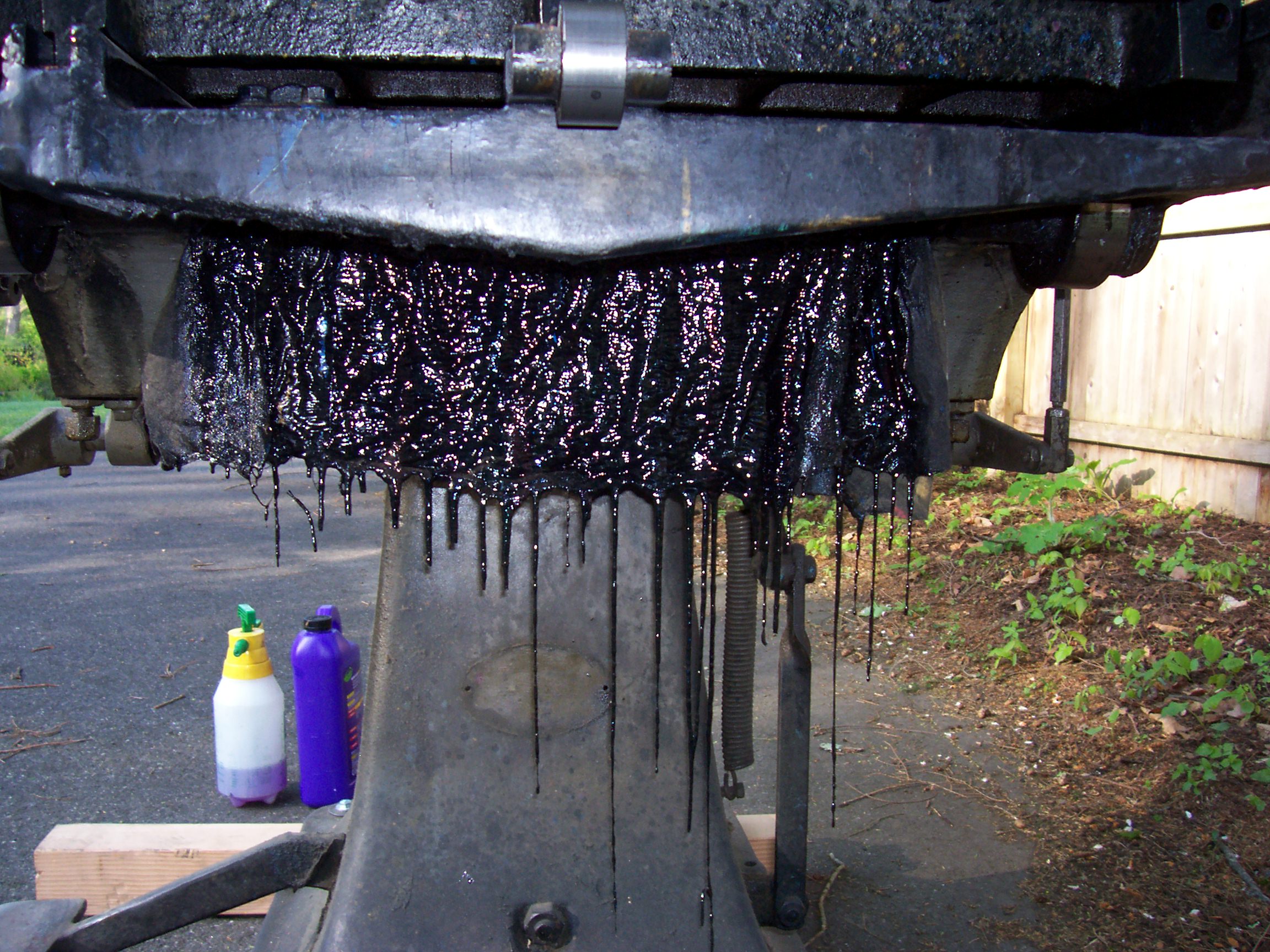
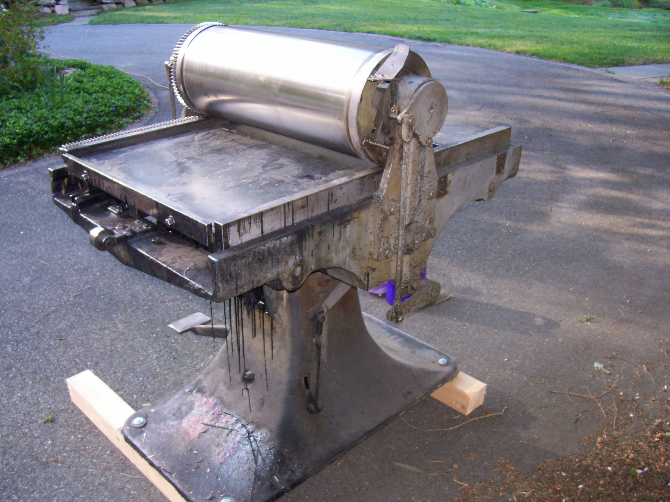
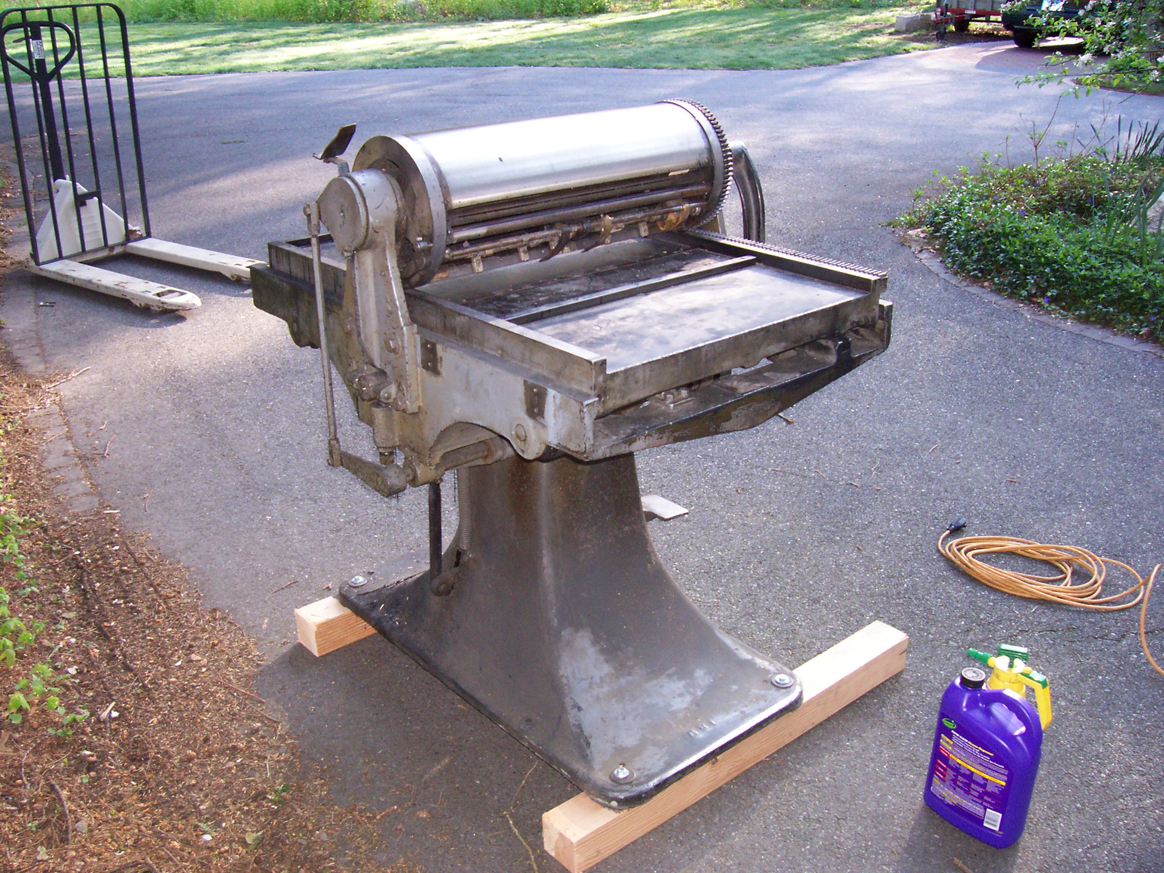
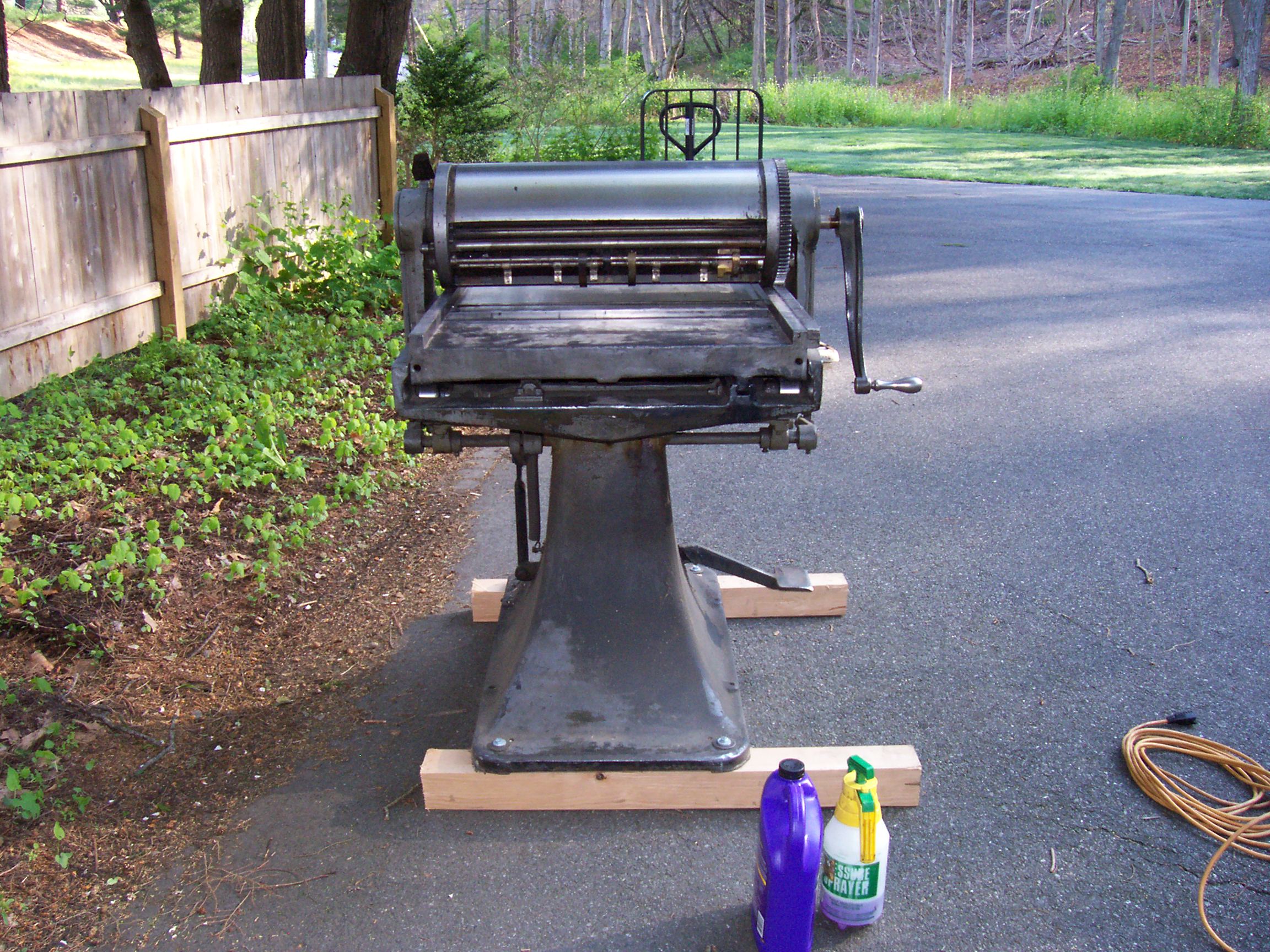
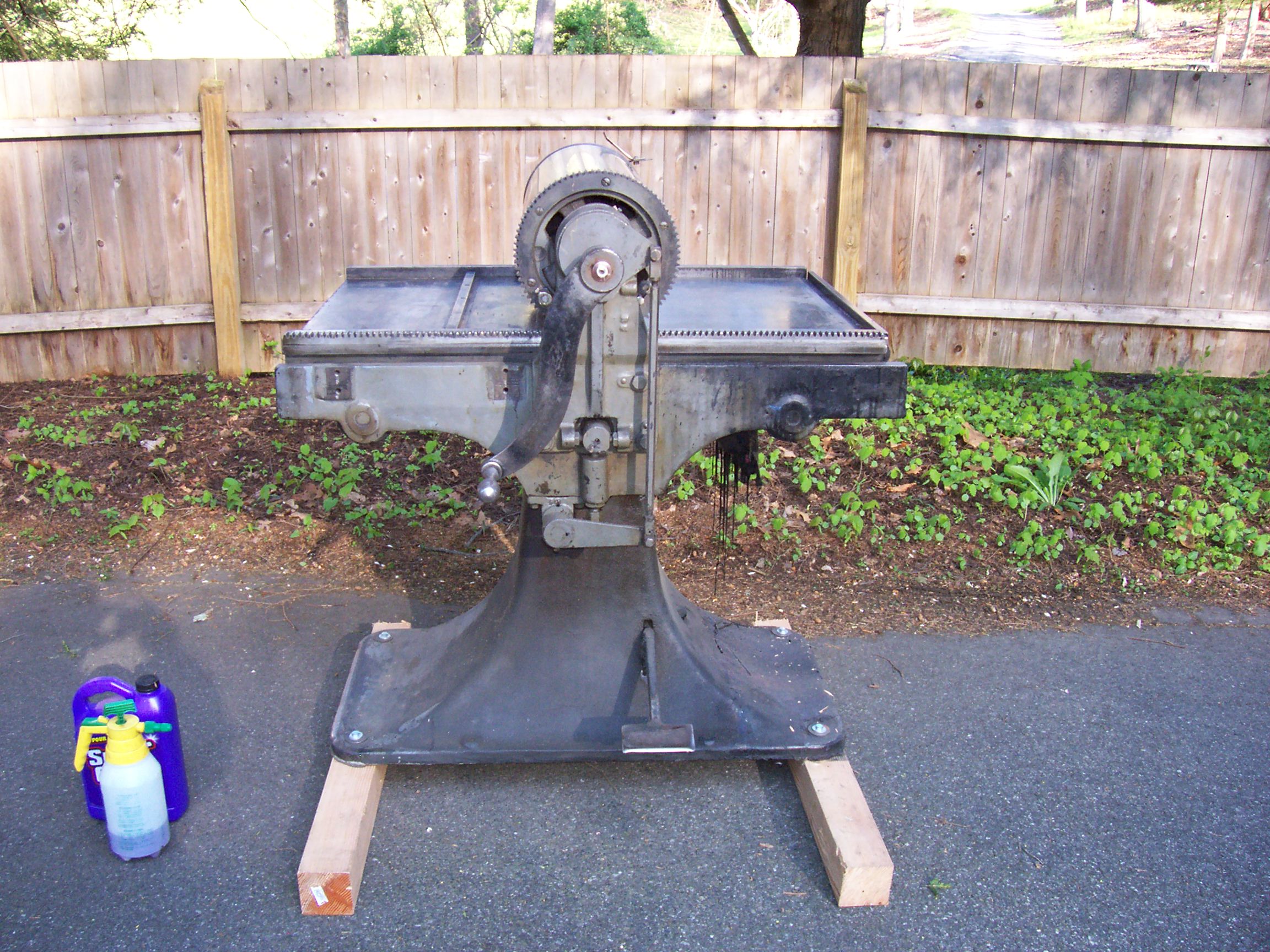
Here is what the press looks like before anything is started except the cylinder blanket has been removed. The plan is to put the press back into original form with all its features working as intended. I may be biting off more than I can chew! There is not much information available to help figure out what the manufacturer intended. It will be part of the fun figuring that out.
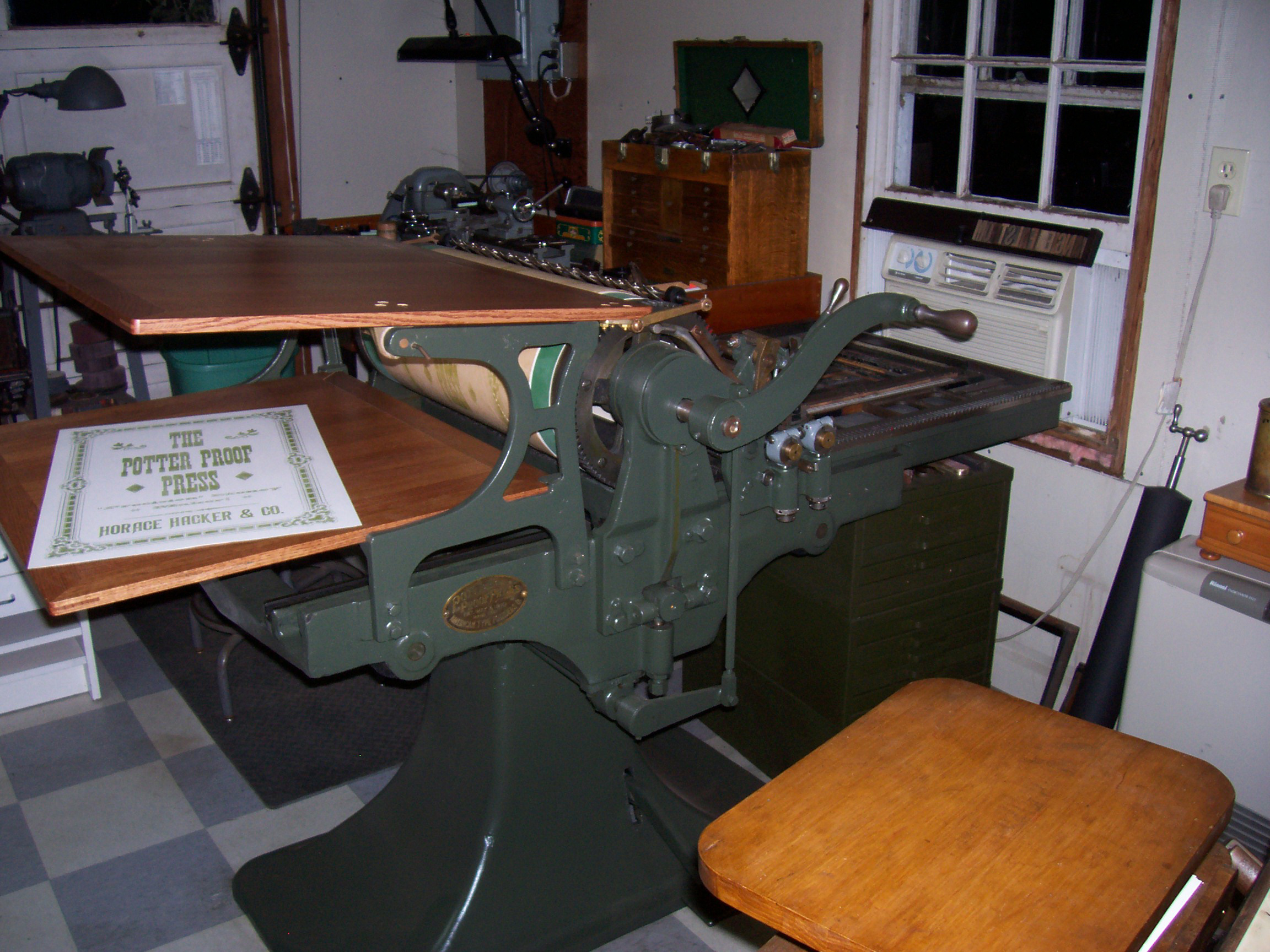
Here is what the press will look like when complete. I really like the look with the massive pedestal and large feed and delivery boards.

The No. 3 has a 25 x 25 print area, is auto inking and auto gripper release. The inking system has a large roller serving as a fountain that has an adjustment feature to control how much additional ink is added to the form rollers each cycle. The grippers are opened at the start of the print cycle by stepping on the foot pedal. The foot pedal also takes the press out of impression to return the cylinder to the print position. The grippers automatically open at the end of the print cycle. You feed paper from the large top feed board and the finished print is deposited on the bottom delivery table at the same time you reverse the cylinder to bring it back to the next print cycle. You do this while standing still in one position unlike the manual Vandercook where you walk with the cylinder as it moves down the bed. The effort required to crank the handle is minimal and much less than you would expect due to properly lubricated and adjusted roller bearings. It moves so well that bumpers are required at the ends of the bed travel as seen below.

Potter bumper detail
Tim and I are fortunate that we have access to some of the missing parts from the Museum of Printing in No. Andover, Ma. The museum has a No. 2 and we were able to borrow some of the parts to either have me make them, or have them cast by a local foundry. I resin cast some of them to send the replicas to the foundry to be made out of bronze or brass depending on the function of the part. The first three pictures below are polyurethane resin prepared to go to the foundry. All holes have to be filled with clay for the metal casting and then drilled and tapped if necessary after they get back. The next four pictures are of actual Potter parts being used to cast new bronze or brass replacement parts. The next picture is of the original ink fountain roller timing gear and my reproduction. And finally, the last picture is of the feed and delivery boards that Tim is having made at a local woodworking shop. We are having the boards done using the same joinery found on the originals. The carpenter reports using 52 dominoes or bisquits in the joints per board.


I have been asked why I would put so much effort into this make and model press. Some think a Potter is a rather crude proof press and I would be better off finding a Vandercook or Challenge. I guess my reason is that I believe when all the original parts are present and working properly that it is anything but crude. I believe the press will ink and register very well, and as previously mentioned, I think the appearance is just amazing. The only issue is getting it back working as intended, and that can be an enjoyable project. The history of Potter and Hacker and their connection is an interesting one. Their names were linked for much of the production of the presses. Nameplates tell the tale, and in the middle of the production of the press the Potter was manufactured by Hacker. If you look at images of Hacker and Potter presses you will see many design similarities. Hacker claims many “firsts” that I thought were introduced by the Vandercook’s. There is more sophistication on a Hacker/Potter than most would realize because there are not many surviving reasonably complete presses. In fact, I only know of one and it’s the No. 2 located at the museum.

Hacker No. 4

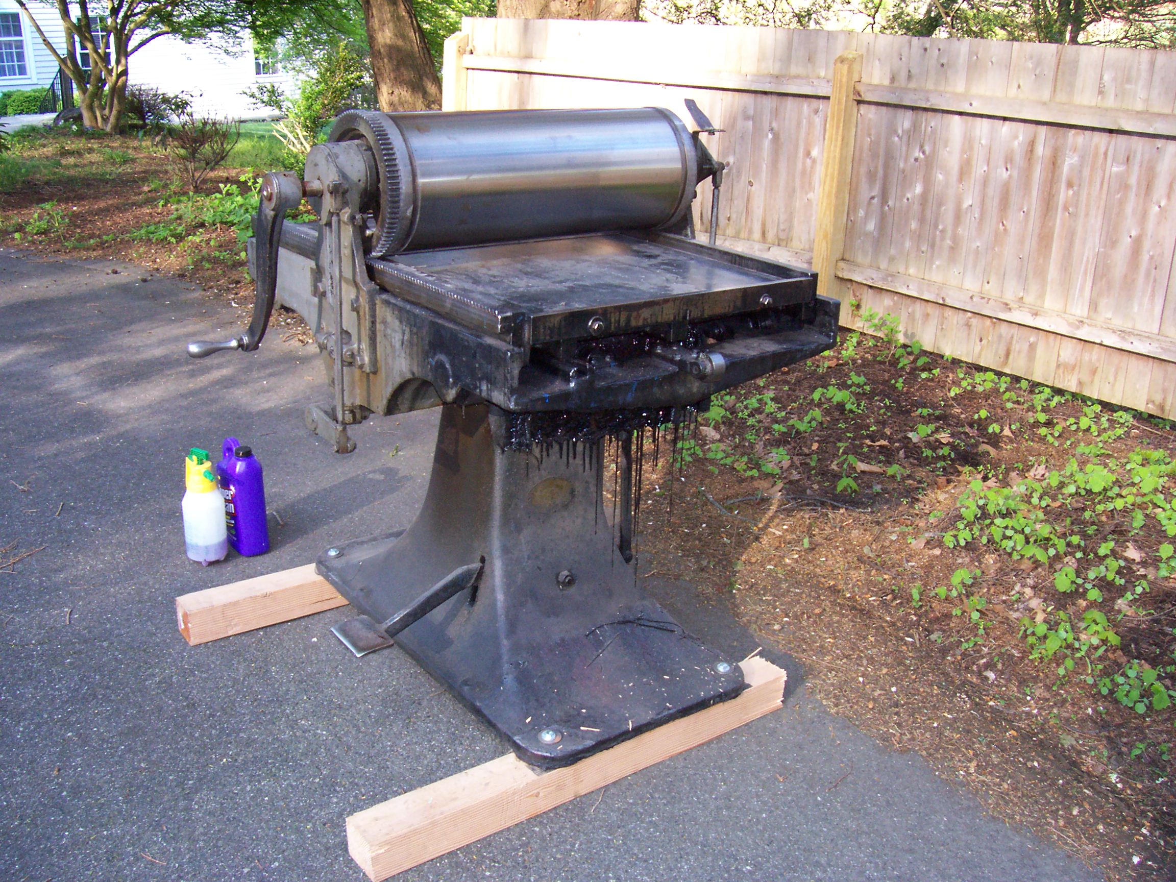
Potter during restoration
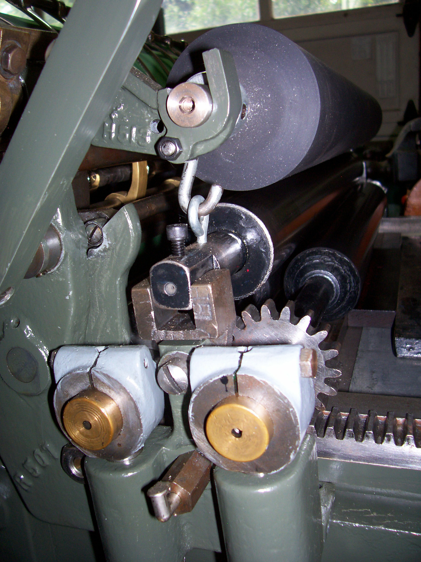
A great feature of the Potter is how easy it is to adjust the form roller height. Here is a picture of the adjusters. You loosen the large round knurled nut on the bottom and turn the smaller dial to raise or lower the height and then tighten the lock nut again. Simple, convenient, elegant.

Form roller height adjusters
I measured the undercut on the cylinder and found it to be .095″ . That’s the difference from the surface of the cylinder to the outside of the cylinder bearers. That’s a bit more than commonly found. Because of this, I elected to put a .065″ underblanket directly on the cylinder and then build up with traditional packing. One benefit of the large cylinder of the Potter is I could actually use red board if I choose. To start out however, I have chosen two sheets of Sun Pack .016 from NAGraphics which is another great source for supplies, and standard tympan. The Potter has two reels inside the cylinder so I can have the blanket permanently attached and play with the packing on top of that without much fuss.

.065 underblanket

Wood type fun!
Here are pictures of the cast parts after some finishing and machining some of the holes and threads and the originals for comparison.

Cast bronze————– Potter proof press parts————– Original

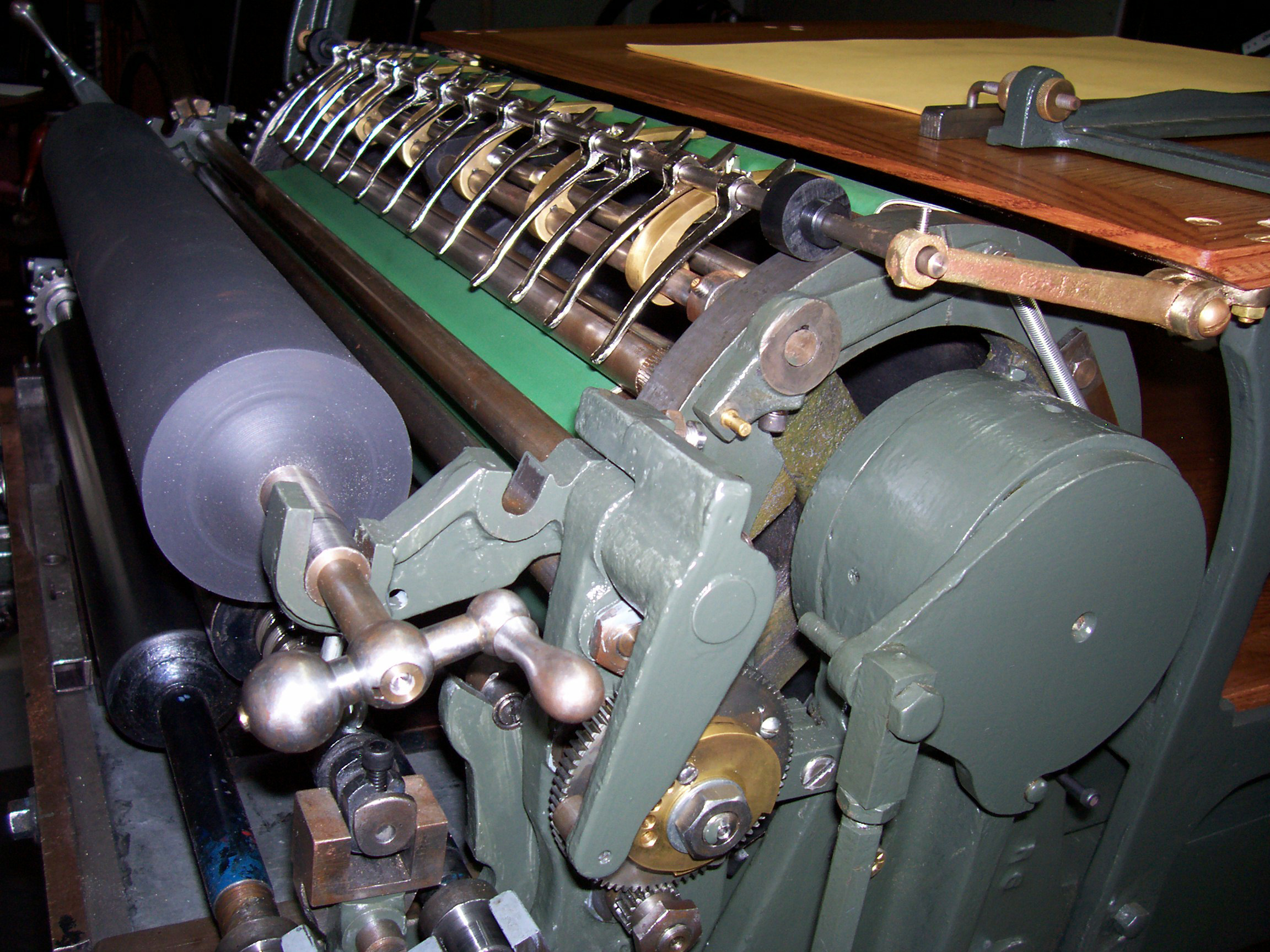
I started work on sanding and polishing the paper guides yesterday (6/5/2012). They don’t look like much when fresh from the foundry, but, with a little effort they really start to improve. The material is silicon bronze which looks a lot like brass with just a bit more red tint from additional copper in the alloy. Took most of the day, but, certainly worth the effort. Here is a before and after shot of a single guide. And then, the whole row of them just sitting on the cylinder. I can’t mount them in their permanent position until the feed board comes back, as the hinges that hold them mount to the underside of the board. That gives me time to get them nickel plated to prevent tarnish.

Before and after

paper guides
Update: 6/19/2012
Well, the feed board is not back yet, but, I have been making some progress on other items and have learned a bit more. The trip mechanism that controls opening the paper grippers has been replicated and installed. Here is a picture of what it looks like.
Original on the right, newly fabricated on the left.

Potter proof press gripper trip
There are a lot of things that can be adjusted to control when the grippers open and shut. I found I could make the grippers automatically open at the beginning and the end of the printing cycle. I had previously thought you were required to step on the foot pedal to actuate the mechanism. I am not 100% sure if I want them to open without stepping on the pedal. I will need to actually do some repetitive printing to have a better idea whether it poses any problems.
Here is a picture of the gripper trip mechanism installed. You can just see it peeking out. It is held in place by the brass bolts.

Trip mechanism installed
Here is a shot of the arm that rotates the grippers. The brass pin on the left side catches in the slots of the gripper trip mechanism forcing the grippers to open when appropriate. There is quite a bit of adjustment available which can alter when the grippers open, or if they open at all. Right now, I have it adjusted so the grippers open automatically when you need to feed a new blank sheet, and when the print cycle is complete. I am not sure if this is how it was intended to operate yet. More to learn.

Potter gripper lever
I finished polishing the paper guides pictured above, and sent them off to be nickel plated. I also spent some time polishing the L shaped pieces that hold the blanket and tympan on the press and sent them off to the plater as well. This is my first experience getting parts nickel plated, so, I am really interested in seeing how they come out. I saw the shipping notice for the ink feeding roller from Ramco Roller Products so that should be here soon. That will complete the inking system. I am now turning my attention to the end paper gauges. These attach to the L shaped pieces previously mentioned and are what you push your paper into from the feed board when first feeding the paper to the cylinder. I believe this is the last fabrication hurdle. I will order some spring steel and begin figuring out how I can best produce them. Sure is fun!
Ink supply system
The ink supply roller came back from Ramco and has been installed. It sits above the metal oscillating roller which distributes ink to the form rollers below.
Ink supply roller
The ink supply roller lowers each print cycle to add ink to the system. How long it stays down in contact with the metal oscillator depends on your setting the brass cam seen here on the metal gear to the lower right of the ink roller. The longer it stays down in contact, the more ink it adds per press cycle. The handle seen on the end of the ink supply roller is used during the initial charging of the system.
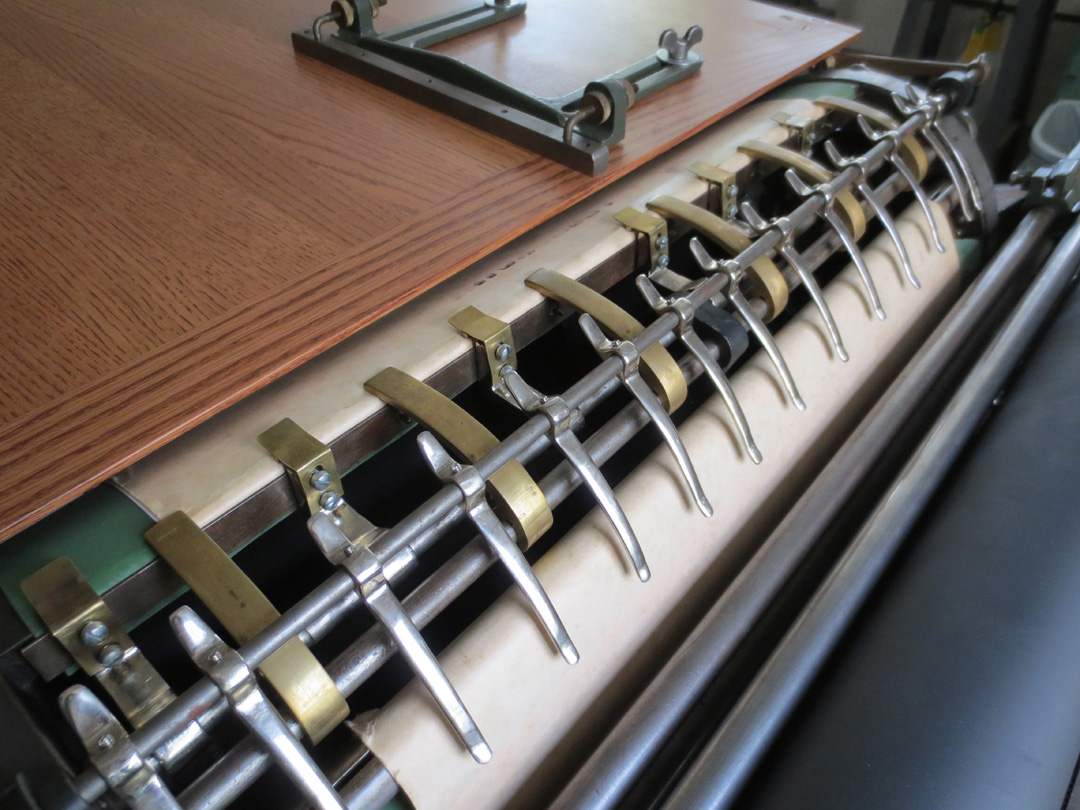
Paper stop, gripper and guide complete
I purchased spring steel to create the paper stops, but, after several attempts decided to switch to brass. I redesigned the stop somewhat to provide a larger stop area that seems to work better. It is less likely to damage the paper with a larger area to push the paper against. Here you can see the grippers, newly nickel plated guides, and the now finished paper stops. I readjusted the press to have the grippers open when you step on the foot pedal and automatically open at the end of the press cycle. The consensus among proof press users is this would have been the correct way to run the press. The feed board is now installed along with the side guide which is also a change I made. The guide is from a perforator and provides better adjustment and longer support than the original system. I added the brass nameplate to proudly display the Potter name.
Finished press!
My first proof proudly advertising my press.
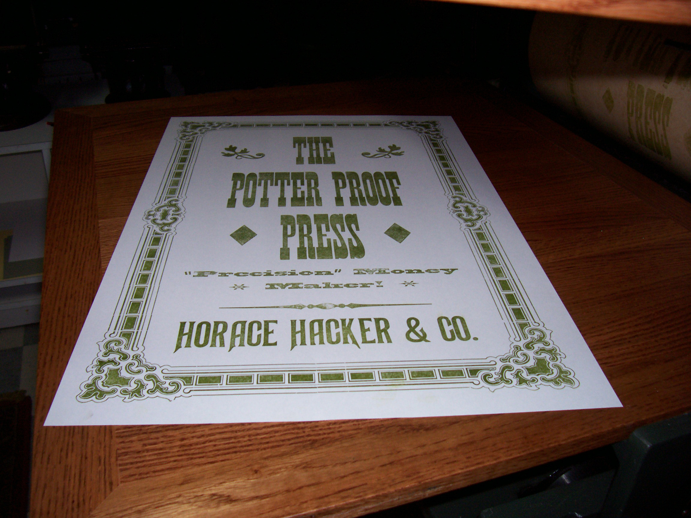
First proof pulled
